This post is follow-up to my proof that the Turtle prototile is not periodic. It is strongly recommended that you read that post first. This post will freely use terms from that post.
When the Hat prototile was first unveiled, one of the first applications was jigsaw puzzles with only one shape of tile. One natural question arises: Given an outline of a patch of tiles, is there always a unique way to fill in that patch with tiles?
While this question was posed for Hat tiles, this is equivalent to the the same question for Turtle tiles. (Section 6 in the Hat paper, a Turtle tile is shown in Figure 6.1). For the rest of this post we be primarily working with Turtle tiles.
For the most general case, the answer is no. Patches as small as six tiles can be filled in in multiple distinct ways, and arbitrarily large patches can do the same.

However, whether such patches can occur in within a tiling of the plane is an open question. This post won’t fully answer that question, but it will show that all multi-tiling patches ‘work’ in the same way. This constrains how such patches may occur on a plane tiling.
To do this, we will describe a method to deduce how a patch is assembled from its outline alone. Of course, this method must sometimes fail, but its failure mode will be instructive. To demonstrate, we’ll start with an outline of a patch of Turtle tiles.

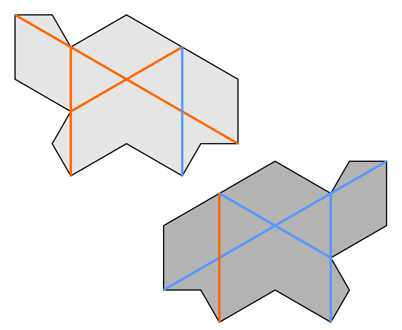
The use of Turtle tiles implies the existence of a consistent spar line colouring decoration(see previous post) for the interior of the patch. Those spar lines and their colours can be deduced from the patch outline alone.

Working with the bare spar lines themselves might be difficult, so we’ll re-decorate the tiles to make it easier.
Ignore the spar colours and the outline momentarily. Starting from the entire planar lattice of spar lines, take their dual to get a periodic tiling of rhombi.

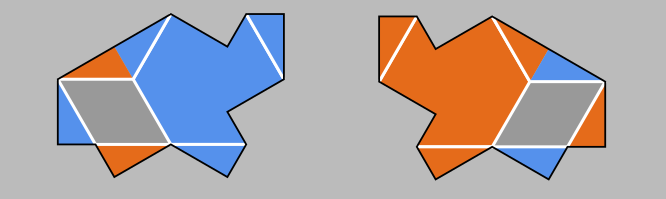
Putting the outline back, we can just accept that outline may cut the rhombus tiling pattern awkwardly. To add the spar line colours back, we can colour the rhombs to signal the corresponding crossing type. To do this properly, we need look at coloured crossings more closely.

The two negative crossings at the bottom of Figure 5 are distinct. They cannot be rotated to match each other and are not even mirror images, since reflection also swaps lead and lag lines. We will need to distinguish them for the rhombus decoration.
Looking at the crossing in the middle of Figure 5, we see that only the bottom left crossing can be a free crossing. The bottom right can only occur as a controlled negative crossing(call this fixed for short). In general the bottom left crossing could also be fixed, but for Turtle tilings it only occurs free. For the rest of this post we will conflate ‘free’ and ‘fixed’ with the two types of negative crossings.
For the two positive crossings, there are no obstacles to simply colouring them with the matching crossing colour. However, recall that positive crossings always come in threes in Turtle tilings. We will group the three matching rhombi together in a hexagon decoration.
The free rhombus will be made up of parts of distinct tiles, some of which could also be used to complete hex decorations. This forces the free rhomb decoration shown above. The fixed rhomb can be chosen to contrast the other decorations.
While it may be simple to decorate a single Turtle tile, for a larger patch we need to guarantee a unique way to assign the positive rhombs to hexagons.

A given positive rhombus can join one of two hexagons. If it lies next to a negative rhomb, the hex containing both is eliminated and we can form the other hexagon. If there are any loose positive rhombs left, then we can treat completed hexagons like negative rhombs to continue. Since all Turtle tiles contain a positive and negative crossing next to each other(see Figure 0), you can always start this process. Also, the positive crossings in Turtle tiles always come in hex-able threes, so the existence of a Turtle tile assembly guarantees we can put all the positive rhombs into hexagons.

To use the hex & rhomb decorations to deduce the internal Turtle arrangement, we need to understand how hexagons and rhombi can lie next to each other. Here it is important to understand that they are only a variant representation of lead and lag lines.

In Figure 10 we see that every fixed rhomb must lie next to exactly two free rhombs and two hexagons. Also, in Figure 7 we see that each Turtle tile adds one hexagon and one fixed rhomb, so on average, each hexagon must lie next to two fixed rhombs.

Figure 7 also shows us that each hexagon must be next to at least one fixed rhomb. Figure 11 implies that at most three fixed rhombs lie next to a hexagon. From the average, the number of hexagons with one fixed rhomb should equal the number with three fixed rhombs.

In Figure 12 above, we start with a hexagon that has only one fixed rhomb to it. This forces the Turtle tile responsible for that hexagon in a specific orientation. This placed tile covers a fixed rhomb, which leaves the next hex with only one available fixed rhomb, which forces another tile placement.
This can continue until we encounter a tile with three fixed rhombs, and we must find another one-rhomb hexagon to continue. However, the tile we just placed removes a fixed rhomb from the end hex, so it acts like a two-rhomb hexagon and can continue the chain if we land on it later on.
For our example patch outline, we are able to force a unique tiling to fill it.


Of course, this procedure cannot work all the time, otherwise Figure 1 couldn’t exist. The only way that the procedure could fail is if there were hex-fixed rhomb loops occurring.

Further discussion
The hexagon and fixed rhomb chains are related to an observation I made several months ago. Imagine that we colour the edges of a Turtle tile by length, dividing its longest edge in half.

Doing this, we divide the perimeter of the tile into 14 line segments that come in two lengths. Note that on adjacent tiles edge colours must match. This can shown if we look at the underlying kite tiling.
We can pair up adjacent congruent segments to form 7 similar angled parts. In Figure 16 the congruent angled parts have the same colour. Focusing on the smaller green parts, two of them are convex w.r.t the tile while one is concave. Three convex parts can fit together neatly, but a concave part forces a single convex part next to it.
This sets up what I call a drainage system in every Turtle tiling. I explore drainage systems in the context of the Hat tile in this thread. The drainage system I discuss here corresponds to what I call ‘chevron drainage’ in that thread.

If we look at the perimeters and hex & rhomb decorations together, we see that the convex parts are all on the hex part, while the concave part is on the fixed rhomb. The concave part forces a hex of one tile next to a fixed rhomb of another. Thus, the chevron drainage system corresponds to the hex-fixed rhomb network.
We can also relate chevron drainage to the original four-metatile system described by the discoverers of the Hat. To do this, we will use a particular tile decoration to illustrate drainage.

We will also need to adjust metatile shapes to fit Turtle tiles. They will still fit with each other in the same way Hat metatiles do.

In Figure 19 there are no loops in the metatiles, and the only ‘outlets’ for drainage occur on the A+ and B+ edges.

Some examination of the metatile substitutions show that loops from crossing A and B edges do not occur. Thus, for a ‘defect-free’ metatile-based Turtle tiling, there are no loops and every finite patch is determined from its perimeter. It remains to be seen how tiling defects alter the picture, but we now know what to look for.
Naturally, one would expect hex & rhomb decorations to be related to metatiles, and that seems to be the case. By observation, the majority hexagons(lead hexagons in the case of the example shown on Figure 9) tend to clump into triangles of 1, 3, or 6. Some further thought and experimentation suggests that only these clusters can occur in a Turtle tiling.
Looking at these triangles together with metatiles, it seems that lone majority hexagons always come from T metatiles, while the 3 central hexagons of a 6-cluster come from the ‘hub’ of a F-metatile ‘propeller’. To be specific, F and X metatile edges alone represent where hexagons lie next to each other.
Throughout this post, I’ve referred to hexagons and rhombs as decorations, because they needed outside context to be placed properly. They can be made into tiles proper by adding bumps and notches to them to enforce proper placement.

For a more general tileset, you can replace the hexagons with appropriately marked rhombi. To match the Turtle tile constraints, we need to ‘glue’ a fixed rhomb to each hex and only use the glued tiles and the free rhomb.

If you enlarge the bumps and notches on the tiles, then they begin to look familiar.

Open questions
What I would really like to see is an equivalent to lead and lag lines for the Spectre tiling. That is, some sort of long-range correlation between tiles like lead and lag lines. Note that the Hat tile breaks the colourability of spar lines, so at least some adjustment would be required if spar lines are used.
The relationship between coloured spar lines, hex & rhomb decoration, and metatiles can also be investigated further.
Acknowledgements
Thanks to Smith, Meyers, Kaplan, and Goodman-Strauss for discovering the Hat monotile and the continuum.
Thanks to Arnaud Chéritat(Twitter), Nan Ma, and Pieter Mostert for the projection app they developed.
Thanks to Robin Houston for inspiring me to investigate hexagons on Turtle tiles.

Leave a comment