This is a rework of a previous post proving that the Turtle tile is non-periodic, to be used as a starting point for further explorations.
A edit has been made to change the defined term ‘irrational’ to ‘arational’ in the post. A follow-up post has also been posted.
In March 2023, an aperiodic monotile was revealed to the public after decades of searching by mathematicians. The unveiled shape, termed the Hat(Figure 0) is strikingly simple.

Given the simplicity of the eventual solution, it seems that if you showed the Hat tile to someone back then, a proof of aperiodicity would quickly follow. A closer look at the announcing paper[1], however, should give us pause.
Of the two proofs of non-periodicity given in [1], one uses software to check cases, which would have been tedious to do back when the question of the aperiodic monotile first arose.

The second proof, while not majorly computer assisted, requires seeing that the Hat tile exists on a continuum of shapes(Figure 1), almost all of which tile exactly the same way as the Hat tile. Given the Hat tile alone, it would take a remarkable leap of insight or a search of other polykites to discover the existence of this continuum and the attendant proof.
Elsewhere on the continuum, there is another shape that, by itself, yields a proof of non-periodicity without excessive case-checking or reference to the continuum.

The Turtle tile is another tile in the continuum (Figure 6.1 in [1]). Like the Hat tile, it is composed of 120°-90°-60°-90° kites, though it requires ten such kites to be assembled. Some particular features of this tile, out of all the tiles in the continuum, lead to a particularly simple proof of non-periodicity.
The Laves sub-tiling

This proof starts from the fact that any Turtle tiling, if each tile is split into kites, yields the [3.4.6.4] Laves tiling. To show this, we observe that a Turtle tile can be made of five ‘gem’ tiles, each made of two kites.

Since every Turtle tile is composed of gems, every Turtle tile implies an underlying gem tiling. The gem tile contain angles of 120° and 90°. The sides are of length 1, 2, and sqrt(3).

Note that the right angles are framed by one rational and one irrational edge. Also, every irrational side has a right angle at one end.
As the right angles are the only ones not a multiple of 60°, they are forced to pair up at least. The lack of acute angles forces those paired angles to lie right next to each other.

The common side of the paired angles must be the same length lest an unfillable acute angle occur(Figure 6). Likewise, the combined edge from the paired angles must meet a matching edge to avoid acute angles. With two short green(rational) sides, a single long green side or another short side pair works, but the only thing that works for two paired irrational sides is another pair of irrational sides.

This, in fact, forces every irrational side to meet edge-to-edge with another irrational side in the same direction, forming regular hexagons from three gems(Figure 7). These hexagons are forced to tile as regular hexagons do, with the only variation being the rotation of the gem tiles within each hexagon.

Cutting the gem tiles into kites extinguishes this variance, leading to the Laves tiling.
Right angles and spar lines
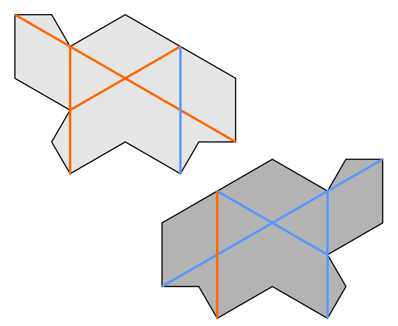
The proof works by looking at how the right angles(reflex or not) of the Turtle tiles must arrange themselves. To this end, we will decorate individual kites with strategic markings as shown in Figure 9.

The line connecting the two right angles is the spar of the kite. The right angles themselves are coloured by their handedness. Each right angle in a kite is made form two sides of different lengths. Look from the ‘inside’ of the right angle, so it appears concave. If the short side is to the right, then it is a lead corner. If that short side is on the left, then it is a lag corner.

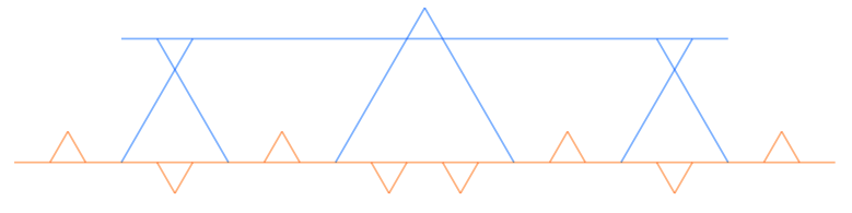
Putting these decorations into the Laves tiling, we see that spars form the continuous lines of a trihexagonal tiling, or a kagome lattice.
These spar lines run in three different directions, forming three line classes. Spar lines intersect each other in pairs, forming three orientations of spar crossings. Let a spar segment be a finite sequence of contiguous spars from a single spar line.
By the symmetry of the Laves tiling, the spar lines are equally spaced and have equal linear density in the three line classes. This symmetry also forces the three line classes to each be the same angle(60°) from each other.
Additionally, each spar line alternates crossings between lines from the other two classes, and these crossings are evenly spaced.

Going along a spar line, we run over a pair of lead corners, across a kite, over a pair of lag corners, across another kite, and then we repeat. Every even number of spars along we are running over the same type of corner.

Zooming in on a single spar crossing, we see a pair of lead corners and a pair of lag corners for four right angles in total. One of the spar lines passing through goes the lag corners, while the other line lies on the lead corners. Taking a broader look(see Fig. 10), we see there are no right angles outside of spar crossings, and every spar crossing looks like this one, except perhaps rotated.
Turtle tiles and spar lines

Using these decorated kites to construct a Turtle tile, we see four distinct spar segments within. Most importantly, each of these segments is an even number of spars in length.
From a previous observation, this means that the ends of each segment in the Turtle tile lie on the same coloured corner. This is not true for the Hat tile, and this is the reason that this proof does not directly apply to the Hat tile.
The fact that does apply to Turtle tiles has has an important consequence for Turtle tilings. For any spar line in the Laves sub-tiling, as soon at it exits one Turtle tile, it enters another one on the same colour corner. As we observed before, it exits that tile on the same colour, and then immediately enters another tile again on that same colour, and so on.
We see that each spar line always moves between distinct tiles when moving over corners of their particular colour. We can thus consistently colour each spar line with that exit corner colour.
Say that a spar line is a lead line if it moves between tiles through a lead corner, and call it a lag line if lies on lag corner when doing so. Let spars and spar segments inherit the designation of their parent line. Again note that every coloured spar line faithfully represents the type of corner it runs over as it pierces a tile boundary.
Since the colour of a spar line is determined within a tile, we can decorate Turtle tiles to match this colouring. As lead and lag corners are chiral, Turtle tiles must be decorated differently depending on their flip. Call a decorated Turtle tile containing mostly lead spars a lead tile, and its flipped version a lag tile.
Colouring the infinitely-long spar lines is a good start, but to move along with the proof these line colour must bear consequences on the Turtle tiling.
A good candidate for that is to look for constraints on spar crossings, which may pin line colours to local conditions. As we don’t have control over the handedness of the tiling, we have to look at achiral properties, such as whether a crossing contains lines that are the same colour or distinct colours.

Call a spar crossing positive if its two lines are the same type, and negative if they differ. In the Laves tiling, spar lines always cross when lying on corners of opposite type. For positive crossings to exist, then there must be a mismatch between a line and the corners underneath.
By the way we’ve coloured the lines, this can only happen if a line is not moving between tiles. In other words, a positive crossing is only possible if one line’s spars right next to the crossing are both in the same tile. These spars are on the opposite sides of the crossing. Thanks to the shape of the Turtle prototile, this is equivalent to a Turtle tile containing at least three out of the four spars next to a crossing. This means that every positive crossing is ‘owned’ by just one tile in any Turtle tiling.
If a tile contains two opposite spars of a crossing, then we say that it is a controlled crossing, and that the tile controls that crossing. If no tile controls a crossing, then it is a free crossing.
Note that while every positive crossing is controlled, the converse is not the case, and controlled negative crossings are possible.
Collated kagome lattices

To look for constraints on spar crossings, let us return to the Turtle tile. A Turtle tile contains 10 kites, thus 20 right angles(internal and external). This means that a Turtle tile is ‘responsible’ for the equivalent of five spar crossings.
A Turtle tile controls four crossings, using only 14 right angles to do so. The two right angles on its long side add half of a free crossing. Of the four external non-reflex right angles, two have to be ‘paid forward’ to complete controlled crossings on other tiles. The other two have no more controlled crossings to complete, so they each contribute a quarter of a free crossing, yielding a total equivalent to five crossings.
Of these five crossings one is free and thus negative. One of the controlled crossings is negative, so three of the five overall crossings are positive. This analysis applies to every Turtle tile in the tiling, so overall we expect exactly 60% of all spar crossings to be positive.
We’ll come back to the positive crossing ratio, but what is more important is how those positive crossings in the tile are arranged. Within each Turtle tile, the three positive crossings, one in each of the different orientations. They are arranged to form the smallest triangle in the kagome lattice of spar lines. Since every positive crossing is controlled by some Turtle tile, then it also must belong to some positive crossing triangle.
Say that a kagome lattice with coloured lines is collated iff there is a partition(i.e. no overlap or loose crossings) of all positive crossings into sets of three, with each set all the same colour, containing one crossing in each orientation forming the corners of a smallest triangle in the kagome lattice.
Another way of understanding a collated kagome lattice is to see how you can re-decorate it to form a rhombille tiling. This substitutes the crossings of the kagome lattice with rhombuses. However, with a collated lattice, you can use just regular hexagons to represent sets of positive crossings, with no rhombi representing positive crossings.
One-colour smallest triangles can also occur that aren’t collation triangles. In that case the triangle’s vertices belong to three separate collation triangles.
What we just showed is that every coloured kagome lattice generated by a Turtle tiling is collated. With this property we can begin to say things about Turtle tilings through their collated kagome lattices.
Theorem 1: Given two negative crossings sharing a line in a collated kagome lattice such that there are no negative crossings between them, then the other two lines of those crossings are not parallel.

Proof: The positive crossings between the given negative crossings are paired up by their collation triangles, as one of the sides of each of those triangles must be the given line. Thus, there are an even number of crossings between our given crossings. This implies that there is an odd distance between the given crossings, thus the other lines of our negative crossings are in different line classes due to the alternation of crossings.

Theorem 2: For any collated kagome lattice with at most two colours of lines, either a colour appears no more than once in each line class, or it appears infinitely often in every line class.

Proof: Assume that there are two or more lines of our colour(say, blue) in one class. If those are the only blue lines, then that violates Theorem 1 directly. If there are finite number of blue lines in each class, collation implies there are an equal number of crossings in each orientation, thus there are an equal number of blue lines in each class. As there are finite blue-blue crossings, a finite circle can cover all crossings. For a not-blue line well outside of the circle, its crossings with the blue lines in the two other classes will be separated, violating Theorem 1(Figure 20).
If only one class has infinite blue lines, then just one of the crossing orientations will have only finitely many examples. If just two classes are infinite, their crossings will extend infinitely far in every direction, and no number of finite blue lines in the third line class can fulfill collation.
Theorem 3: Given a collated two-colour kagome lattice, if the fraction of each colour in one line class is well-defined, then it is well-defined for all three and each line class has the same proportion of colours.
Proof: Suppose we have a line class with well-defined colour proportions and a line class we want to test. Choose a witness line in the last line class. If there are only finitely many lines in each each class with a different colour than ours then we are done. Otherwise, choose a secondary parallel witness line with a different colour to the first some small distance away.
Every line in the classes we are checking crosses both of our witness lines. Lines with the same colour as our first witness line form positive crossings and thus collation triangles. These triangles allow us to ‘link’ pairs of lines in the classes forming the positive crossings. For the differently coloured lines, collation triangles on the secondary witness line can pair these lines up(See Figure 21).
The result is a bijection between the line classes where line colour is preserved and given the right shift(i.e. choosing the right witness lines), the ‘distance’ between two paired lines is bounded. This is enough to show that the second line class shares its colour ratios with the first. This argument also works for the last line class.
Arationality and non-periodicity
Given Theorem 3, the ratio of line colours in each class in a Turtle tiling takes paramount interest. This is where the positive crossing fraction we calculated earlier can help. First we see how two quantities are related. Let 

Given two spar line classes, the frequency of lead lines in each is
There are two ways a crossing can be positive: lead-lead and lag-lag, with frequencies of 


The solutions of this equation are:

What matters at the moment is not the exact solutions but the fact that there are no rational solutions. It can also be shown that the ratio of the two colour’s frequencies is also irrational.

Say that a two-colour kagome lattice is arational if the fraction of lines in each class that are one colour is irrational or not well-defined. The discussion above proves that any Turtle-derived kagome lattice is arational. This allows us to prove the main theorem.
Theorem 4: No Turtle tiling has a non-trivial translation symmetry.
Proof: A translation symmetry for the Turtle tiling forces the generated kagome lattice to also have that symmetry. The non-trivial symmetry will cause some non-zero shift by 
Corollary: No Turtle tiling is periodic.
This covers half of a proof that the Turtle tile is aperiodic. The other half can be adapted from Section 2 of [1] with modifications to the metatile shapes(Figure 22). I might be able to force these metatiles to arise several posts down the line.

If I do end up doing this, the fact that Turtle-derived kagome lattices are collated and arational will be the starting point. The restrictions that collation and arationality place on Turtle tilings run much deeper than what I describe in this post. That is what I will cover in the next post.
References
[1] D. Smith, J. S. Myers, C. S. Kaplan, and C. Goodman-Strauss, “An aperiodic monotile,” Mar. 2023, doi: https://doi.org/10.48550/arxiv.2303.10798.

Leave a comment